
What Digital Stationing Actually Is
Digital stationing is a relatively new category, with products that operate very differently internally, even though they share similar marketing language. Buyers who do not know what to ask often end up paying for one product while operating another. This article explains what the category truly includes and highlights the key questions that distinguish genuine digital stationing from approximations marketed under the same name.
What to look for in a digital stationing platform:
Native handling of station equations, including both gap and overlap equations, with the back and ahead designations preserved through every report and export. This is the single most important test.
A setup model where the platform arrives ready for the field, rather than one that requires your team to publish data, build forms, or configure structures before a crew opens the app on a new project.
Engineered alignment geometry preserved from the source design files, including spirals and circular curves, rather than approximated as short straight segments.
The project's native coordinate system respected, rather than forced into a generic web map projection.
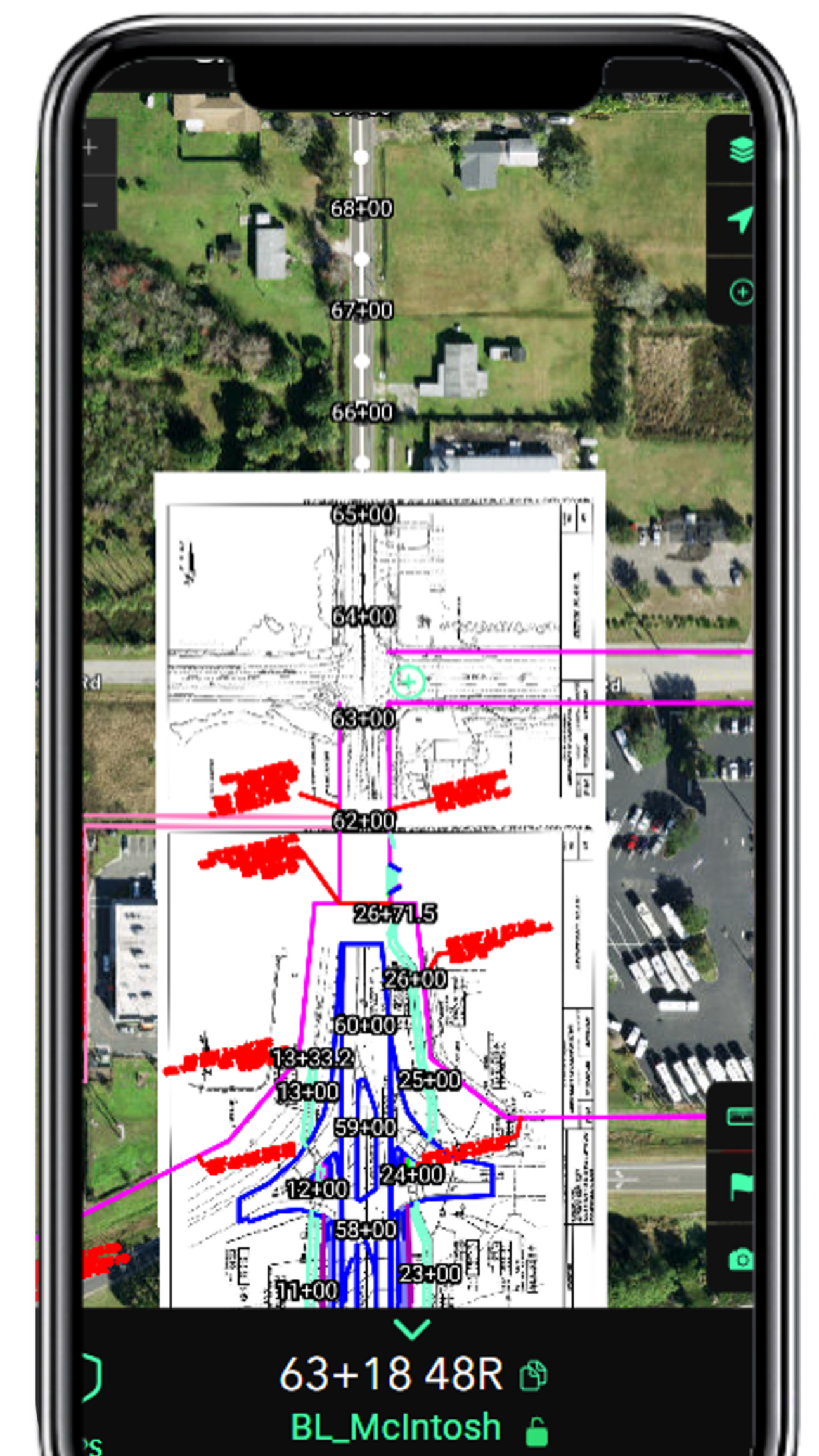
Plan sheets and design layers (utility, grading, drainage, structures) linked to the user's current station, rather than a basemap with a few features dropped on top.
A shared project library that every party on a project can access, rather than a system in which each organization rebuilds the same alignment for its own team.
If a vendor's answer to any of these questions is vague, the platform is solving a different problem than the one you intend to buy it for. The rest of this article explains why each test matters and what to listen for in the vendor's response.
How the Category Emerged and Where it Splits
Roads are designed, built, paid for, and disputed in the language of stationing. Every point on a road project has a station and an offset along the alignment, and every contract document, plan sheet, pay item, and change order references those two numbers.
Digital stationing is a category of software that displays the alignment on a phone or tablet. Before this category existed, the numbers lived inside CAD software and in the heads of the survey crew. Field staff read stationing from physical stakes set by surveyors and measured between them by hand. Accuracy depended on the stake being placed correctly and the measurement being made carefully. Digital stationing makes the alignment available to everyone on the project in real time, with accuracy that ranks just behind that of a high-precision rover. The category is young enough that the products within it are still defining what counts. Two platforms marketed as digital stationing can produce very different field experiences and project records.
Here's a straightforward way to understand the difference between platforms in this category. Everyone has flown on an airplane. Seat numbers indicate where to sit. They serve two purposes: either recording your seat after the flight for accountability if issues arise, or guiding you to your seat during boarding, helping two hundred people board efficiently. Both uses are helpful, but only one ensures everyone ends up in the correct place.
This distinction gets lost between the people who design road projects and the people who build them. Designers see the alignment in the CAD file and assume the field already knows where to be. Field crews know that finding the right place is the real challenge, not recording it afterward. Digital stationing platforms split along the same line. Some are built primarily to record where work happened. Others are built to tell the field where work needs to happen, in real time, as the plans are drawn. The distinction is invisible until the field crew opens the app and tries to do their job.
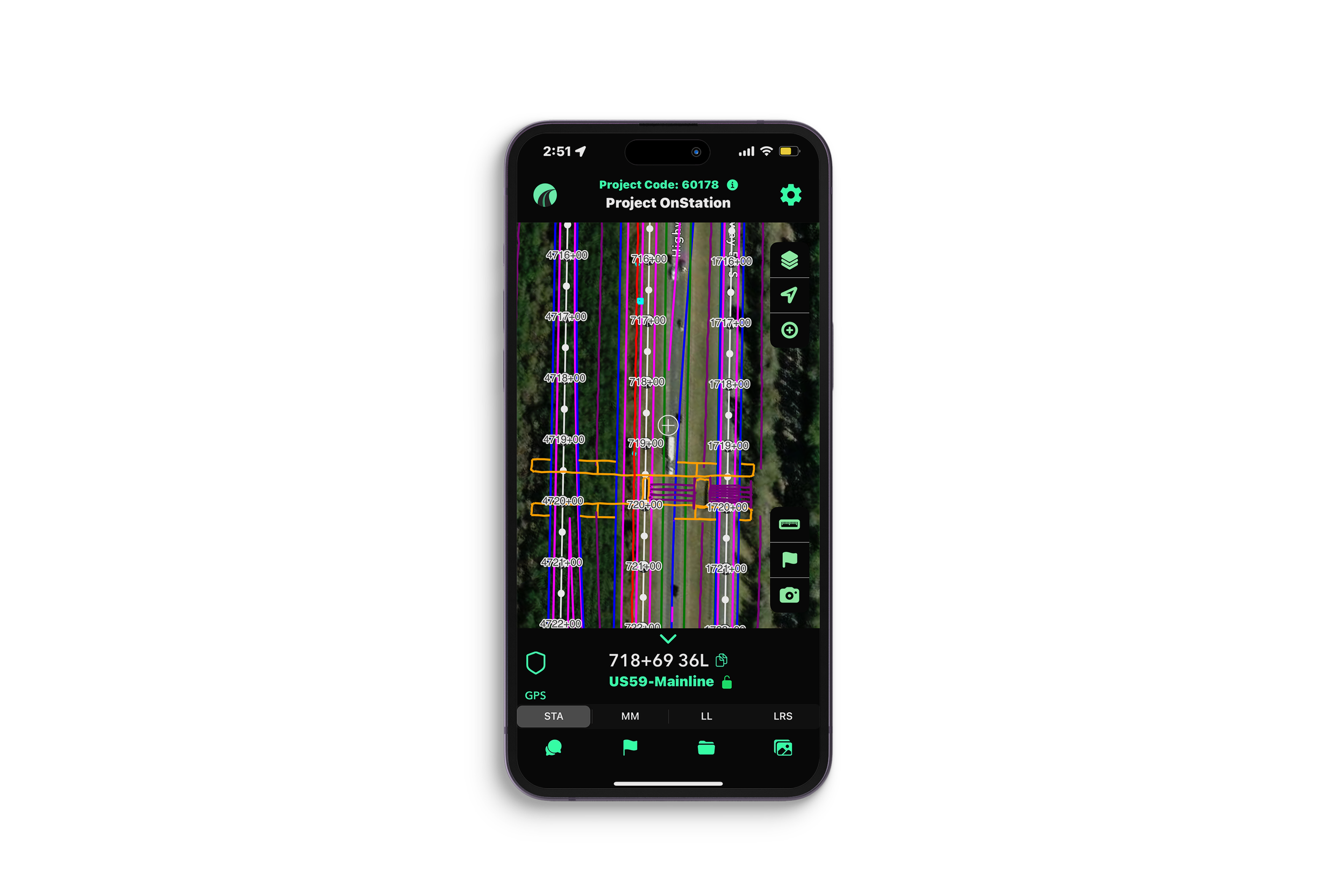
Live digital stationing on a phone. The alignment, stations, tick marks, and labels render from the design file as one layer, with the user's live station and offset at the bottom of the screen.
What the Term Covers
At a minimum, a digital stationing platform tells a person on a road project what station and offset they are at on their phone, without needing a stake or a survey crew. That is the floor.
Beyond the floor, platforms in this category differ across four key dimensions that become especially important once the project is underway.
Whether the engineered alignment is preserved or merely approximated
Whether station equations are a primary feature or a workaround
Whether the field reading updates live from GPS or only when the user taps a point
Whether the platform arrives ready for the field or requires per-project configuration
Each dimension remains unseen during a brief demo but becomes crucial when the project faces its first challenge. Buyers unaware of what to ask often end up paying for one product while operating another.
The Most Important Test: Station Equations
If you take one thing from this article, take this. Ask any vendor how their platform handles station equations.
A station equation is a point on an alignment where the station value changes abruptly while the physical geometry continues unbroken. It is expressed by equating the station approaching the point (back station, BK) to the station departing the point (ahead station, AH). Two cases occur:
Gap: ahead station > back station (e.g., 105+00.00 BK = 110+25.43 AH)
Overlap: ahead station < back station (e.g., 142+50.00 BK = 138+00.00 AH)
Equations are introduced for specific design needs: tying into an existing route with established stationing, joining independently designed segments, or realigning a stretch whose new length differs from the original while preserving the downstream stations that plans, ROW, utilities, and structures already reference. They're common on reconstruction, widening, and tie-in projects, and even a mill-and-overlay can inherit one at a junction. Most DOT projects include at least one, and many have several.
This test is crucial because most platforms in this category rely on a general-purpose mapping data model not designed for alignment. In this model, stationing is simulated by storing a measure (m-value) at each polyline vertex that must increase monotonically. However, a station equation represents a break in this progression, which the data model cannot naturally accommodate.
When a platform based on that model encounters an equation, two unfavorable options arise. The first involves smoothing the equation by allowing distance values to continue increasing across the break, which causes downstream stations to report incorrect numbers offset by the equation, with errors accumulating for each additional equation. The second option is to split the alignment into separate segments at every equation point, ensuring correct stationing within each segment but making revisions manual, disrupting continuous reporting across equations, and preventing the representation of overlapping equations.
Real digital stationing accurately reads the equation table from the source design delivery and maintains it. Both gap and overlap equations are correctly reported. The back and ahead designations are preserved in reports and exports. When an alignment is revised, the field team sees the updated equations automatically, without needing to rebuild anything.
In practice, this functions as a binary test: a platform either reports the correct station on both sides of each equation with the designations intact or it does not.
Two station equations rendered live in a single project view. The stationing resets across each break the way the plans defined them. Most platforms in the category cannot represent this natively.
Who Does the Setup?
The second dividing line is operational, not technical. When a project arrives, who does the configuration work to make the platform usable?
In one approach, the customer's team handles the process. An individual with GIS or CAD skills takes the engineering deliverables and converts them into the platform's data structure. Feature layers must be published, permissions set up, and final linework shared within the team. The fieldwork cannot begin until the office completes their part, and this process is repeated for each new project.
In the alternative model, the platform accepts engineering deliverables in their original format and is prepared for field deployment. The customer just submits the project, and the vendor ensures it becomes ready for use. This reduces setup efforts for the customer and removes the dependency on a GIS resource being available.
This operational question impacts whether the licenses you acquire are actively utilized or left unused. Field tools that depend on office configuration cycles can often get lost among manual methods, such as the trusted measuring wheel and printed PDFs. Conversely, tools designed to minimize deployment friction from the beginning generally see faster adoption.
Another operational consideration is that in the customer-configured model, a project created by one organization is accessible only to those the organization explicitly shares it with. The prime contractor, CEI, and DOT each rebuild the same alignment for their respective teams. In contrast, the vendor-configured model builds the project once and makes it accessible to all involved parties. Having everyone work from the same location points and design files significantly improves project workflow efficiency. OnStation has developed more than 5,000 projects, many of which were submitted directly by DOTs. When a new contract starts on an existing alignment, field crews can access it immediately on day one without any configuration changes. In this scenario, the project itself, not the organization, is the unit of work.
To determine the platform's requirements, ask the vendor what steps your team must take before a crew starts a new project. If the vendor mentions tasks such as publishing data, creating expressions, setting up forms, or building structures, it indicates that configuration is needed. Conversely, if the response is simply "submit the project" or to access the project inventory, it falls into the other category. This distinction is essential, especially when deciding between a per-project solution and a scalable, all-in-one project management.
The customer submits the engineering deliverables; the platform handles ingest, alignment rendering, and configuration before the crew opens the app.
The Engineering Criteria
Three other dimensions distinguish the platforms in the category. They matter less than equations and setup, but they are what the engineer or surveyor on your team will sanity-check.
True alignment geometry: Engineered horizontal alignments are defined by three fundamental geometric elements: tangents (straight sections), circular curves, and spiral transition curves (clothoids). Clothoid spirals are precise mathematical curves where curvature increases linearly with arc length. A platform that reads the engineered geometry preserves the alignment as designed. A platform that approximates curves by stringing together many short straight segments, a common shortcut in general-purpose mapping platforms, introduces measurable stationing drift between the displayed station and the true station. On a long horizontal curve, that drift is real.
Coordinate system preserved: Road projects live in state plane, county-specific, or custom coordinate systems, often with a combined scale factor applied. A platform that respects the project's native coordinate system produces readings that match the CAD file. A platform that forces every project into a single common map projection can introduce mismatches that the surveyor catches only after the dispute.
Plans and design layers are linked to the alignment: Construction crews work from plan sheets, but the sheets are only part of what they need. Real projects also include utility layers, grading plans, drainage layouts, and structural details. A platform that links the current sheet and the relevant design layers to the user's current station matches how field staff actually work. A platform that shows only a basemap with a few features layered on top forces the user to switch manually between the app and the plans. Connecting design data to the alignment is what makes the platform usable for the work itself, not just for finding a station.
Equation context preserved: Every station equation has two sides, a back side and an ahead side, with different station values. A field note logged at or near the equation point belongs to one side or the other, and which one matters for the contract. A platform that preserves the side designation through every report and export keeps the record defensible. A platform that drops it produces a station number that, at an overlap, cannot be uniquely placed back on the alignment.

Questions to Ask Any Vendor
If you are evaluating a digital stationing platform, these are the questions the demo will not surface on its own and that cleanly separate the platforms in the category.
How does your platform handle station equations? Specifically, what happens at an overlap equation where the ahead station is less than the back station?
When an alignment is revised and an equation moves, what does my team have to do to update the platform?
What does my team do before a crew opens the app on a new project?
What formats do you accept the design deliverables in? LandXML, ALG, DWG, DGN, KML, TBC, TIFF.
Does the platform preserve the project's native coordinate system, or force the project into a common map projection?
Are spirals and circular curves carried as engineered geometry or as densified segments?
Does the platform connect the design layers (utility, grading, drainage, structures) to the alignment, or only show a basemap with features layered on top?
If a foreman is standing on the back side of an equation, what does the app show, and how do I know it is correct?
Where OnStation Sits
OnStation founded the digital stationing category and built the platform based on the key points in this article. Equations are faithfully represented from the original source. The engineered geometry is maintained, and coordinate systems are respected. Plans and design layers are linked to the alignment. The customer submits the project or accesses the extensive project inventory, and the field team begins work shortly thereafter.
If you are evaluating digital stationing, we welcome the comparison on every question above. Schedule a demo or start your access period.